Instructions for Modbus RTU communication in Yaskawa inverter with Delta DVP PLC
1. Modbus standard communication in the industry:
Modbus is a serial communication protocol developed by Modicon published by Modicon® in 1979 for use with its programmable logic controllers (PLCs).
Because of signal transmission in serial mode, it also helps to save signal wiring and increase transmission rate (from 9600 to 19200 baud). Modbus is a popular standard and has many documents for reference, so it is easy for the newcomer to reach it.
2. Yaskawa GA700 inverter:
This is a new generation inverter which is inherited and promoted the tradition of high-quality Yaskawa inverter series introduced in 2016
- Power range from 0.4-315 (kw).
- Built-in braking unit up to 75kW, EMC filter, DC reactor reduces noise.
- Enable wireless connection to install and monitor via Bluetooth port (option).
- RS485 communication port in available. Other option: Profibus, profiler, Ethernet …
- Degree of protection standard is IP20. Can require for higher protection options according to the needs of the factory.
- Built-in keyboard with LCD helps to display more information and easier to observe and control.
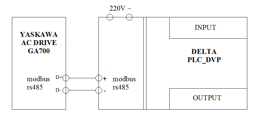
3. Connection diagram between Yaskawa inverter and Delta PLC :
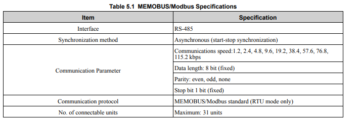
4. Setting the Modbus communication parameter for Yaskawa GA700 inverter:
| Code | Function | Value |
| H5-01 | Address of the inverter | The default is 1 |
| H5-02 | Transmission Speed | [3] 9600 Baud |
| H5-03 | Party/Stop bit | [1] Even Parity |
| B1-01 | Reference frequency | [2] Reference by
Modbus Communication |
| B1-02 | Control method | [2] Control by
Modbus Communication |
5. Basic communication register of Yaskawa inverter
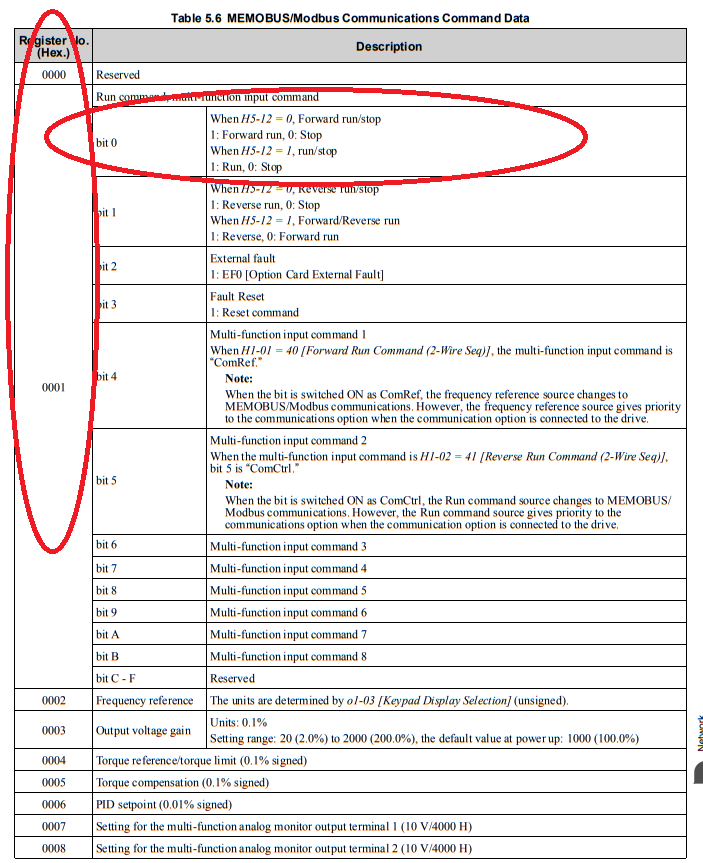
For example: How to transfer the Run command to the drive based on the above communication address table? We notice the 2 highlighted columns.
The first column is the registered address of the drive here selected as 0001.
The second marker column is the value we will transmit down to the drive to receive the execution command. Here the function bit 0 release the Run signal for the drive. We set the BIT 0 value from 0 to 1, but we do not use BIT 1-BIT 16, so we set the value of BIT 1-BIT 16 is 0. So the value that the PLC sends for the drive is 0000000000000001 = 1.
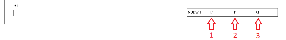
1: The address of the drive wants to transmit down.
2: Address register in the drive.
3: The value is written in the drive register.
6. Installation instructions and communication commands on PLC Delta:
A. Set the communication on the Delta PLC with the WPL Soft software
Fortunately, the Delta PLC supports communication so the implementation is quite simple. We only need to be aware of the simple steps below, the communication commands will automatically appear on our program.
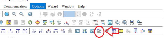
Step 1: Select the circle icon shown below.
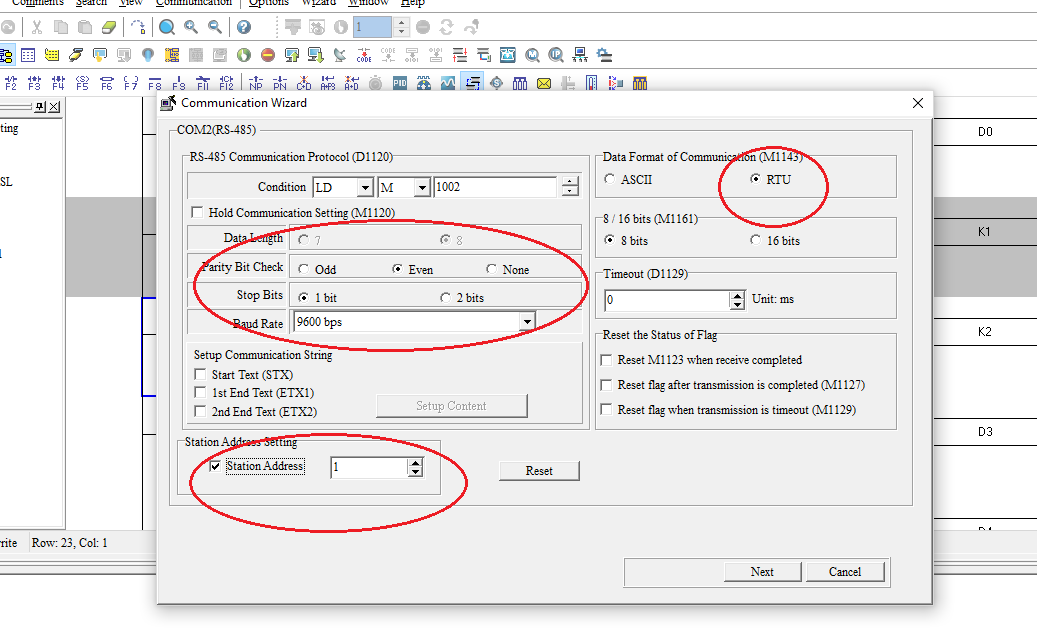
Step 2:
- The address configuration table on the PLC will appear
- Note: the circled part between the inverter and PLC must be the same.
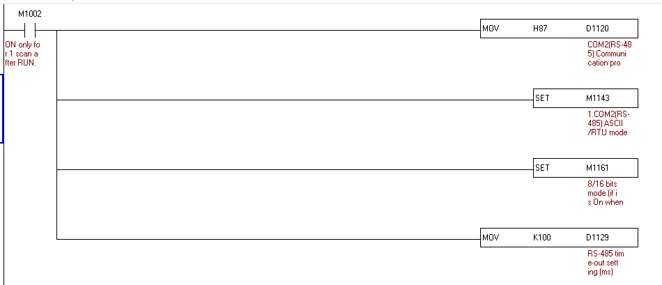
- After installation is complete, the communication configuration commands will automatically appear as shown in Figure 5 and we only use communication commands on the PLC to read and write values to the inverter.
B. Some examples of reading and writing values from PLC to Yaskawa inverter register.
Commands are written in PLC:
Require: When X0 signal is available, the inverter will Run
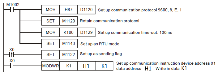
Explain:
- The command line after the M1002 flag is used for traditional installation (Speed, number, address …)
- When the signal X0 is available, PLC will write the value K1 to H1 register on the inverter, at that time the address of the inverter is 1.
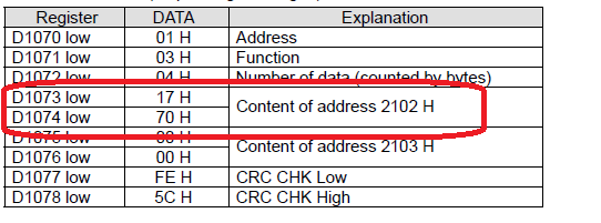
The command for reading value on PLC:
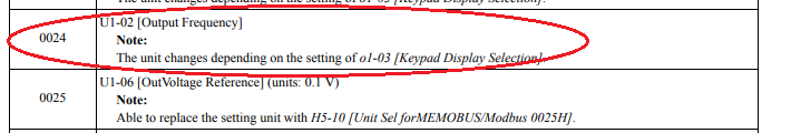
Require: read the inverter output frequency through Modbus communication.
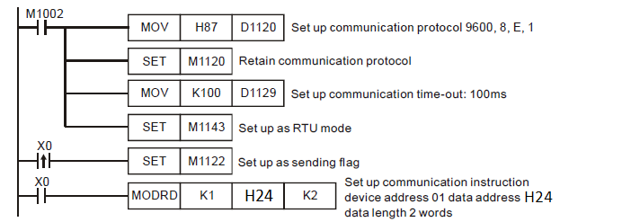
Explain:
- When there is X0 signal, PLC will execute a value read command from the inverter’s H24 register with the MODRD command, with the inverter address being 1, the data size being 2 words.
- The read value will be saved to D1073-D1074 register of PLC. Then we can use the Move command to move that value to another register to process, or display via HMI, SCADA …