
Tension Control Inverter
- PURPOSE
In production lines, there are many stages that require a running engine to create a constant tension on products. To meet the needs, there are two possible solutions:
- Use of torque motor: The torque motor has the advantage of allowing the motor to hold electricity even when inactive. However, torque motors have small power consumption drawbacks. Especially the engines are not available in the stock so it is difficult in case of replacement. In addition, the quality of torque motor depends heavily on the process of motor magnetization and the requirement of specialized controllers in production.
- Using AC motors running with inverters: This solution provides a simpler solution when repairing or replacing. With the development of AC motor control technology, the inverter enables the control of the motor moment to produce the exact output required. It is also suitable for systems that require both speed control and moment control. Besides, AC motors and inverters can be easily maintained, repaired or replaced as well. This solution allows the use of both asynchronous 3-phase motors as well as PM synchronous motors. That depends on the needs of customer.
- CALCULATION SELECTION OF MOTOR POWER
To build the system, the first thing we need estimate engine power and speed. Then we choose the type of inverter and capacity accordingly. Based on production needs, required tension forces, mechanical system specs to calculate exact engine power. For example, the roll slitting system as below:
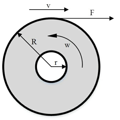
Parameters of the system:
– Max diameter of slitting lot: 2R = 2m
– Min diameter of slitting lot: 2r = 0.4m
– Max length speed: v = 600 m / min
– Max tension: 2000 N / m
– Max roll size: 2.7mI.
- Calculate motor speed:
– The smallest circumference of the discharge lot: 2 x 3.14 x r = 3.14 x 0.4 = 1,256 m
– Max rotation speed of motor at the time of smallest discharge: 600 / 1,256 = 478 rpm
– Choose the gear ratio is 1: 3 with 4 Poles engine (1490rpm)
- Calculate motor power
– The max pulling force is F = 2000 x 2.7 = 5400 N
– The maximum torque on the shaft of the gear is Tn = F x R = 5400 x 1 = 5400Nm
– The maximum torque on the output shaft of the motor is Tm = Tn / 3 = 1800Nm
– Motor power is calculated according to the following formula:
P = T * n / 9.55 = 1800 * 1490 / 9.55 = 280 kW
In which: P is the motor power
T is the maximum torque on the motor shaft
n is the maximum motor speed
Therefore, the motor parameters will be 315kW power consumption with 4 poles
- Solutions:
Tension control inverter can control motors operating in diverse ways depending on using needs.

Basing on system requirement, we have many diverse solutions.
For systems which do not require high accuracy. Examples are cable acquisition systems. Use inverter with control function of open-loop torque (FC360, GA700 …). Select the inverter with the right capacity of the motor. Based on feedback of current and voltage value, the inverter automatically calculate the interpolation to generate the torque value at the motor shaft end. Compared with the moment set point, the inverter adjusts the motor torque to touch the requirement. The disadvantage of this solution is that not all kind of inverters allow open-loop torque control. In addition, since the feedback calculations are interpolated, the value of the output torque at the motor may not be exactly for the high accuracy. So this solution does not apply to running requirements that need high precision, brittle as the paper industry.
- Use inverter to control closed-circle torque. Similar to the above solution, but the engine is installed encoder speed feedback. Combination of motor speed feedback signal and electricity value, motor voltage. The drive can calculate the motor output moment This solution provides higher accuracy. However, this solution only calculates the moment generated at the motor shaft. Therefore, for some systems, the set point moment value operation needs adjusting depending on the load. For example, roll slitting system. When newly operated, the coil diameter is bigger than the value of set point moment, which must be high, low speed. In the process of operating, coil diameter is gradually decreased so the set point value is decreased, the speed is increased.
- Use inverter to control closed-circle torque combined with tension feedback signal. This solution allows the PID to control the tension value of the load at the desired position. This is the most optimal solution, for high accuracy. The system accurately controls the tension at the load position to the desired value during operation.
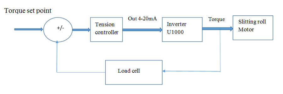
– System block diagram:
Depending on systems, tension control can use specialized control package or PLC or can be programed inside inverters.
The pros of this solution is accuracy, tension setpoint value set only once, no need changing during manufacturing process.
NOTES:
In order that inverters can run in torque control mode, the inverters must identify motors.
Limited speed: Inverter must set up the limited speed of the motors. As torque disappears, the motors will spin up to the speed.
Adjust torque compensation value at limited speed, low speed